A reducer does more than join two pipe sizes. It changes the physical path of the line, which can affect centerline elevation, drainage, venting, available straight length, and the way a connected pump, valve, spool, or equipment nozzle fits. The first question is not simply which reducer is on the shelf. It is whether the job needs a centered transition or an offset transition.
That is the practical difference between a concentric and eccentric reducer. A concentric reducer keeps the smaller pipe centered within the larger pipe. An eccentric reducer shifts the smaller pipe toward one side and creates a straight, or flat, edge. Both can reduce a line from one nominal size to another, but their geometry is not interchangeable in a horizontal run.
This guide explains how to compare the two shapes, what to check before choosing one, and what details should appear in an aluminum reducer quote request. It is a selection guide, not a substitute for the piping design, governing specification, or engineering approval for the actual service.
Start with the piping geometry
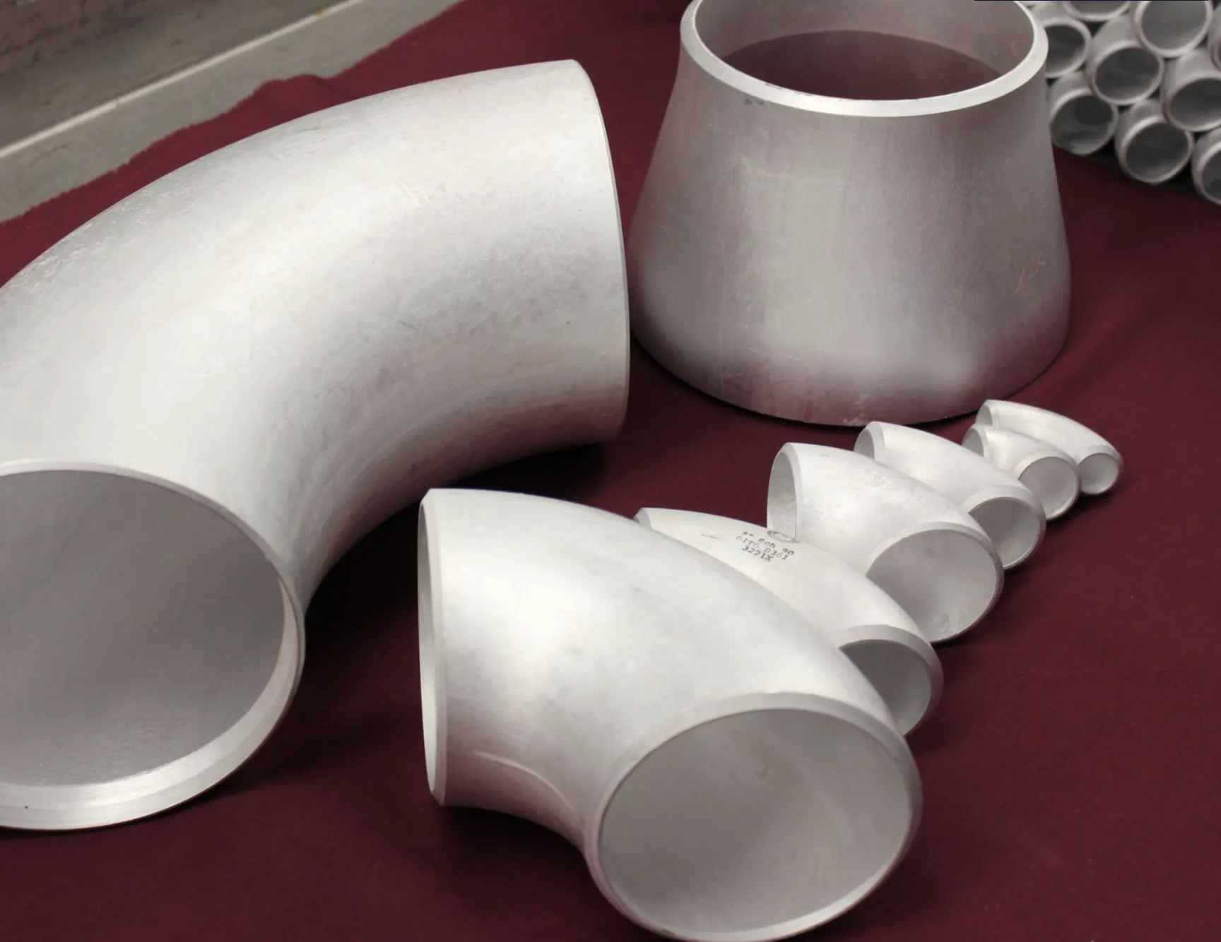
A concentric reducer is symmetrical. If the large and small ends are viewed head-on, their center points line up. The result is a tapered transition that changes the diameter while holding the centerline. That makes the concentric shape a natural starting point where the pipe centerline needs to remain continuous, particularly in vertical runs or arrangements where a high point or low point inside the transition is not a concern.
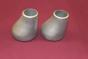
An eccentric reducer is asymmetrical. The centerline of the smaller end is offset from the centerline of the larger end, leaving one side of the reducer straight. That straight side can keep the top, bottom, or another outside surface of the pipe aligned through the size change. This is often the decisive difference when a horizontal line must manage air, vapor, liquid, solids, pipe-support elevation, or a fixed equipment connection.
Both reducer types are used in butt-weld piping systems. The applicable fitting and material requirements still matter. ASME B16.9 covers overall dimensions, tolerances, ratings, testing, and markings for factory-made wrought butt-welding fittings. For aluminum work, the governing purchase documents should also identify the alloy, temper, wall and material requirements rather than relying on the reducer shape alone.
Before comparing a catalog part, locate the reducer on the drawing and identify what cannot move. That may be a vessel nozzle, pump connection, valve, support elevation, existing pipe, flange face, drain point, or downstream spool. The fixed relationship will usually make the concentric or eccentric choice much clearer.
When a concentric reducer is the practical choice
A concentric reducer is usually selected when the piping layout needs the smaller line to stay centered on the larger line. It provides a centered, tapered change in diameter, which is straightforward to describe and review on a drawing. In a vertical line, the centered geometry is often convenient because the transition does not create an intentional offset from one side of the pipe to the other.
The same reasoning can apply in a horizontal line when the design has adequate drainage and venting provisions and the centerline is the dimension that must be held. The key point is that the reducer should follow the piping design. It is not a rule that every horizontal line needs an eccentric reducer, and it is not a rule that a concentric reducer is only for vertical pipe. The actual service, slope, flow direction, connected equipment, and elevation requirements determine the right geometry.
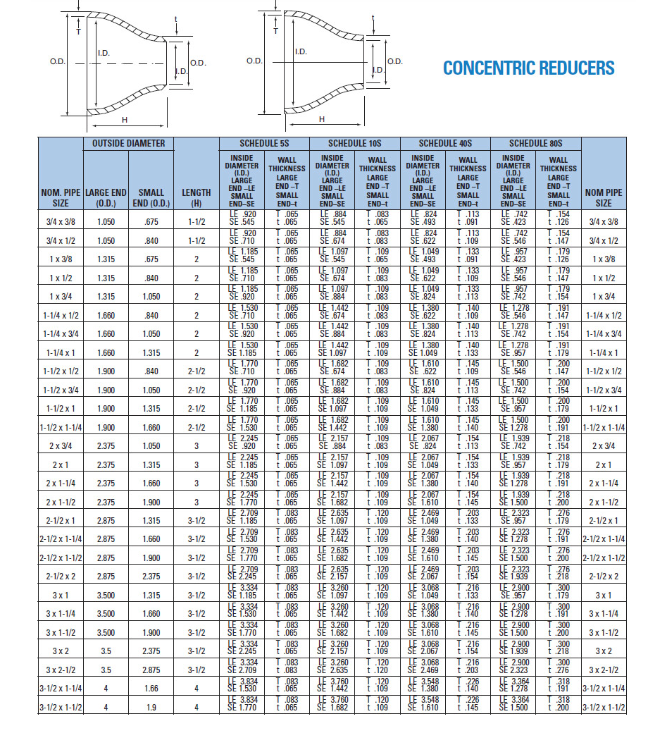
Use the site’s concentric reducer dimensions as an initial dimensional check. The chart can help compare the large and small nominal sizes and the fitting length before the final order description is prepared. It does not replace the issued drawing, piping class, or project requirements for wall, end preparation, material records, testing, or inspection.
For a centered transition, confirm that the pipe route still has the required clearance after the reducer is installed. A reducer can affect the available straight length for welds, the location of a nearby support, insulation space, instrument access, or the position of a companion fitting. The centerline may remain continuous while the outside diameter changes, so surrounding clearance still needs to be checked.
When an eccentric reducer is the better fit
An eccentric reducer is used when one side of the piping needs to stay aligned or when the line must avoid collecting material at the transition. Its flat side gives the designer a way to control the pipe profile through the change in size. That can be important where a horizontal line must avoid a pocket, preserve a bottom-of-pipe elevation, keep the top of pipe aligned, or meet the approach geometry for connected equipment.
The orientation is part of the specification. A request for “eccentric reducer” without a drawing or a flat-side direction can leave a critical detail open. The correct orientation depends on where liquid, gas, vapor, or solids could accumulate and how the line approaches the next component. What looks like a small rotation at the fitting can change whether the system creates a high point or low point.
This is especially important at pump suction. Guidance often uses flat side up for a horizontal liquid suction line where the objective is to avoid trapping vapor near the pump, but that is not a universal installation rule. The source location, flow direction, line slope, phase behavior, solids, and pump arrangement can all change the required orientation. The drawing and responsible engineering review should govern the final callout.
An eccentric reducer can also be selected to maintain a practical support line or a fixed elevation through a horizontal change in size. That is valuable in a crowded rack, a replacement installation, or a fabricated spool where the downstream pipe cannot move. Instead of treating the offset as a generic preference, identify exactly which outside surface needs to stay aligned and show that requirement on the drawing.
Do not reduce the choice to flat side up or flat side down
“Flat side up” and “flat side down” are useful shorthand only after the service and piping arrangement are understood. They are not a substitute for a design decision. The same eccentric reducer can be installed in different orientations depending on whether the line needs to pass vapor, drain liquid, avoid solids buildup, preserve a pipe elevation, or approach a pump from a particular direction.
For example, a common horizontal pump-suction arrangement uses the flat side at the top so the transition does not create a vapor pocket at the high point near the pump. But a source located above the pump, a line carrying solids, or a layout that must preserve a different outside elevation can lead to a different approved orientation. The job is to avoid unwanted accumulation in the actual system, not to repeat a shop rule without checking the drawing.
The practical review should ask four questions: What is flowing through the line? Which way is it flowing? Where can gas, vapor, liquid, or solids collect? Which pipe elevation must remain consistent? Answer those before setting the orientation. Then mark the flat side and flow direction on the isometric, spool drawing, or purchase description so the intent does not get lost between estimating, purchasing, fabrication, and installation.
Compare the dimension charts before releasing the part
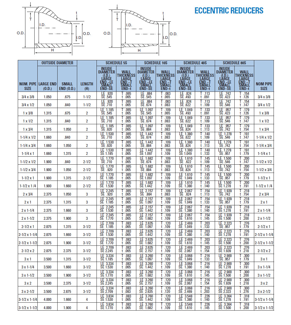
A reducer description begins with two nominal sizes, but the fit-up depends on more than the large-end and small-end callout. Check the fitting length, the end diameters, schedule or wall thickness, and the relationship to adjacent pipe. On an eccentric reducer, also check the offset and orientation. A correct nominal size can still put the next connection in the wrong location if the geometry has not been reviewed against the assembly.
For a standard aluminum butt-weld reducer, use the full fitting dimension charts to compare the available geometry. The site separates the concentric reducer chart from the eccentric reducer chart, which makes it easier to review the intended shape rather than treating every reduction as the same component.
In a retrofit, take the review one step further. Identify the actual outside diameter, wall, line elevation, and end condition of the existing pipe. Confirm whether the replacement needs to line up with an existing support, valve, flange, or fabricated spool. A centered transition may not land at the same elevation as an offset transition, even when the pipe sizes on both ends are identical.
For a new fabrication package, confirm the reducer with the neighboring components at the same time. An elbow, tee, flange, straight length, or valve can create a clearance problem that is not visible in a reducer chart alone. The best time to resolve that is before material is cut or welded, while the quote can still reflect the actual assembly.
Choose the reducer from the application, not the part name
Two jobs can use the same nominal pipe sizes and still need different reducer geometry. A vertical riser that must keep the line centered has a different constraint from a horizontal transfer line approaching a pump. A gravity-drain line has a different concern from a pressurized process line. A replacement spool in a tight rack may be driven by existing pipe elevation, while a new installation may be driven by the equipment nozzle arrangement. The component name alone does not contain those facts.
Begin with the direction of the run. In a vertical run, a concentric reducer is often the straightforward geometry because it maintains the centerline through the transition. In a horizontal run, examine whether the line needs a controlled top or bottom profile. If it does, an eccentric reducer may be the better starting point because the flat side can hold a chosen outside elevation. The final choice still belongs to the approved design, especially where the service has pressure, temperature, flow, cleanliness, or reliability requirements.
Next, identify the condition that must be avoided. In liquid service, a high point can create an unwanted place for gas or vapor to collect. In a line carrying solids or slurry, a low point can create a place for material to settle. In a system with a critical pump suction, the transition geometry can affect how the line approaches the suction connection. In a fabricated pipe rack, the concern may be entirely mechanical: the pipe must clear a support, valve handle, cable tray, or adjacent spool.
Then identify the dimension that controls the assembly. Some drawings hold the pipe centerline. Others hold top of pipe, bottom of pipe, or a specific connection elevation. An eccentric reducer lets the design preserve one outside line while changing diameter. A concentric reducer holds the centerline instead. Marking that dimension on the drawing prevents a buyer from selecting the right sizes but the wrong geometry.
Finally, separate a standard fitting selection from an engineering decision. A supplier can help review a complete callout and published dimensional range, but the supplier should not be asked to guess the system’s drainage, venting, pump, or process requirements from a bare size description. When the job documents are unclear, resolve the design question with the responsible engineer before treating either reducer type as an automatic substitution.
Common reducer selection mistakes to avoid
The most common mistake is assuming that concentric and eccentric reducers are interchangeable because both connect the same nominal pipe sizes. They are not. The different centerline geometry can move the downstream pipe, create a different pocket inside a horizontal line, or change how the assembly reaches an equipment nozzle. A size match is only one part of a fit-up check.
Another mistake is specifying an eccentric reducer without showing its orientation. “Eccentric reducer, 6 in. x 4 in.” identifies the taper but does not say where the flat side belongs. The completed fitting can be rotated in the field, but that is not a reason to leave the drawing unclear. Orientation should be explicit before fabrication, not decided at installation after the piping route is already committed.
It is also risky to treat a pump-suction rule of thumb as a universal answer. Flat side up is commonly discussed for certain horizontal liquid suction arrangements, but a piping system may have different flow direction, equipment elevation, drainage, or solids-handling needs. The sound practice is to identify the unwanted condition, review the actual approach to the equipment, and follow the approved design.
Buyers also sometimes list only the large and small nominal sizes, leaving out schedule, wall, alloy, end preparation, and construction requirements. That description is not complete enough for a butt-weld fitting. The wall relationship affects fit-up, while alloy and temper affect the material requirement. A reducer that is correct in profile but incorrect in wall or material is still the wrong fitting for the job.
Finally, do not use a reference chart as the final approval for a custom reducer. Standard charts are useful for planning a known geometry. They cannot establish a special taper, added tangent, nonstandard wall, eccentric orientation, machining detail, or the exact relationship to a fabricated spool. When the part differs from the standard range, attach a drawing that identifies what must be held.
Keep material, wall, and end preparation in the same decision
Reducer geometry does not establish material compatibility. A complete aluminum reducer request identifies the required alloy and temper, nominal sizes, schedule or wall, end preparation, and the fitting construction or documentation requirements that apply to the job. Aluminum Pipe Fittings lists 5086 H32 and 6061 T6 aluminum fitting alloys, but alloy selection should follow the piping specification and service requirements.
Wall and schedule deserve the same attention. A reducer that matches the nominal pipe sizes but does not match the required wall can create an unsuitable butt-weld fit-up or add fabrication work that was never part of the original scope. State the schedule or direct wall thickness for both ends where the project requires it. Do not assume that a reducer’s wall is implied by the larger line size.
For factory-made aluminum and aluminum-alloy welding fittings, ASTM B361 is the material specification to review. The standard covers factory-made wrought aluminum and aluminum-alloy welding fittings and calls for the specified alloy and temper. Use the standard as a specification check, then make sure the final order documents still state the actual geometry, wall, alloy, construction, testing, and record requirements for the project.
The site’s ASTM B361 reference page provides a plain-language starting point for aluminum fitting requirements. For any controlled project, follow the current edition required by the contract and the project’s own piping documents. A standards reference cannot fill in a missing reducer orientation or choose the correct alloy for a specific service.
Know when the reducer needs a custom review
Standard reducers are a sensible starting point when the large and small nominal sizes, wall, alloy, end details, and geometry all match the published range and the drawing. A custom review is appropriate when the job needs a larger size, a special taper, nonstandard wall, unusual end preparation, added straight lengths, a specific orientation, or a reducer that must integrate with other fabricated components.
Custom work is also worth reviewing when the reducer sits in a critical tie-in or a tight assembly. A line can appear straightforward on a material list while the actual installation depends on a fixed flange face, a vessel nozzle elevation, a support spacing, or access for welding and inspection. In those cases, share the isometric or spool drawing rather than asking the supplier to infer the controlling dimensions from two pipe sizes.
Describe which dimensions are fixed and which can follow standard shop tolerances. Note the flow direction, large and small ends, required straight lengths, wall, alloy, bevel, material documentation, inspection needs, and delivery target. For an eccentric reducer, show the flat side directly on the drawing. Clear information turns a vague reducer inquiry into a fitting request that can be reviewed accurately.
Aluminum Pipe Fittings supplies stock fittings in 5086 H32 and 6061 T6 from 1/2 in. through 8 in., with custom fittings, flanges, and pipe available up to 48 in. The published aluminum butt-weld fitting range is the right place to start for standard configurations, then the drawing can define the custom details that matter.
Prepare a quote request that identifies the right reducer
The goal of a quote request is to let every reviewer see the same requirement. Start with concentric or eccentric. Then list the large and small nominal sizes, alloy, schedule or wall, end condition, quantity, and delivery need. If the reducer is eccentric, include the required orientation and flow direction. A marked-up drawing is more useful than a line item that leaves the flat side open to interpretation.
Include the surrounding context when it controls the decision. That can include the pump suction nozzle, valve, adjacent reducer, flange, support line, existing pipe elevation, or a full spool drawing. If inspection, material test reports, special packaging, or a particular construction class is required, put that in the first request. It is easier to review the complete scope before a quote is issued than to retrofit key requirements later.
How Aluminum Pipe Fittings can help
Aluminum Pipe Fittings helps buyers review the geometry and specification details that determine whether a reducer will fit the actual piping job. Start with the published concentric and eccentric reducer dimension charts, then compare the fitting with the drawing, required alloy, wall, and surrounding connections.
For a standard configuration, the aluminum butt-weld fittings page outlines the published fitting range. For a package, a replacement, or a custom reducer, use the quote request page to send the sizes, alloy, wall, orientation, drawing, quantity, and delivery timing. That gives the sales team the information needed to discuss a practical fitting path.
Frequently asked questions
What is the main difference between a concentric and eccentric reducer?
A concentric reducer keeps the centerlines of the larger and smaller pipe aligned. An eccentric reducer offsets the centerlines and has one straight side. The selection depends on the required piping elevation, flow path, drainage or venting needs, and the project drawing.
When is an eccentric reducer used?
An eccentric reducer is commonly considered on horizontal piping when the installation needs to keep one side of the pipe aligned or avoid a high point or low point that could collect gas, vapor, liquid, or solids. The required orientation depends on the actual service and piping arrangement.
Can a concentric reducer replace an eccentric reducer?
Not automatically. A concentric reducer changes the centerline geometry and can create a different high point or low point in a horizontal run. Any substitution should be reviewed against the piping drawing, service conditions, elevation requirements, and equipment connection before material is ordered.
Which way should an eccentric reducer face?
The flat-side orientation must follow the approved piping design and the actual flow conditions. A common pump-suction arrangement may use flat side up to avoid a vapor pocket near the suction, while other layouts can require a different orientation. Do not specify flat side up or flat side down as a universal rule.
What information is needed to quote an aluminum pipe reducer?
Provide the concentric or eccentric configuration, large and small nominal sizes, schedule or wall thickness, alloy, butt-weld end details, quantity, drawing reference, orientation for an eccentric reducer, delivery location, and needed-by date.