Pipe fitting dimensions are more than chart values. They determine where the pipe run turns, where a branch lands, how much straight pipe remains for welding, and whether a replacement or new assembly will actually fit the available space. A fitting can have the right nominal size and still create a problem when its center-to-end, overall length, outlet position, or end detail is left unchecked.
The fastest way to make sense of a dimension chart is to identify the fitting type first, then read the dimension that controls that fitting’s geometry. After that, match the nominal size, wall or schedule, alloy, connection, and drawing requirements. This guide explains that sequence for common butt-weld elbows, tees, reducers, and caps.
Start by separating size from geometry
Nominal pipe size tells you which pipe the fitting is intended to join. It is not the same thing as every outside measurement you may take with a tape or caliper. For a butt-weld fitting, the outside diameter at the bevel must match the mating pipe, while the fitting’s shape has its own measurements that control layout.
Geometry answers a different set of questions. An elbow needs a center-to-end distance. A tee needs run and outlet center-to-end dimensions. A reducer needs a large end, small end, and overall length. A cap needs enough height and end detail to close the run without interfering with adjacent equipment. Treat size and geometry as two checks, not one.
The fitting dimension charts on this site are a practical place to begin. Use the chart for the actual fitting style, then check the final requirement against the piping drawing, material list, and project specification before ordering.
Read elbow dimensions from the centerline
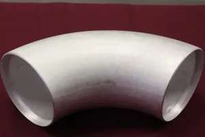
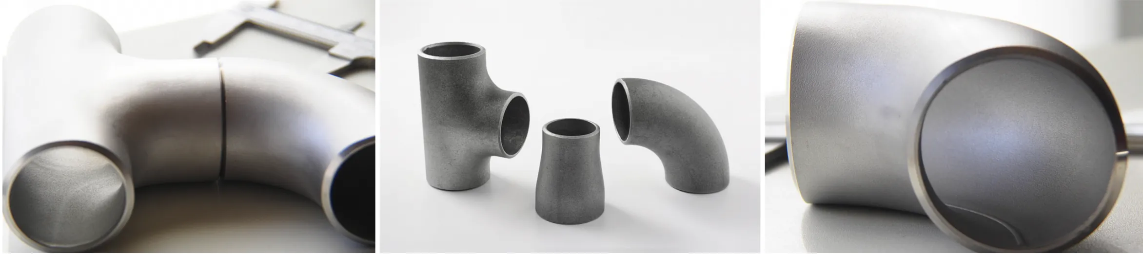
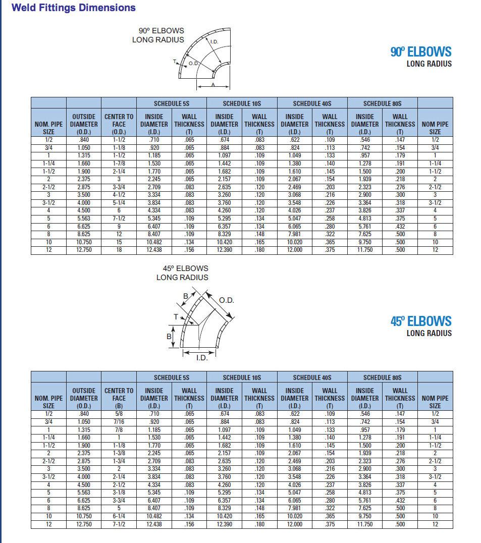
For an elbow, the useful layout number is generally the center-to-end distance. It tells you how far the fitting extends from the centerline of the turn to either welding end. That measurement affects cut length, clearance, support location, and the position of the next component in the run.
Long-radius and short-radius elbows are not interchangeable. A long-radius elbow uses a broader sweep and is commonly selected when the layout and flow path call for it. A short-radius elbow turns more tightly, which can help in restricted space but changes the takeoff. The exact type, angle, nominal size, wall, and alloy should all appear together in the callout.
Use the long-radius elbow chart or the short-radius and return chart to check the reference geometry. Then compare the center-to-end value with the approved drawing. A chart is useful for planning, but the drawing controls a restricted-area installation or any modified fitting.
Check both dimensions on tees and crosses
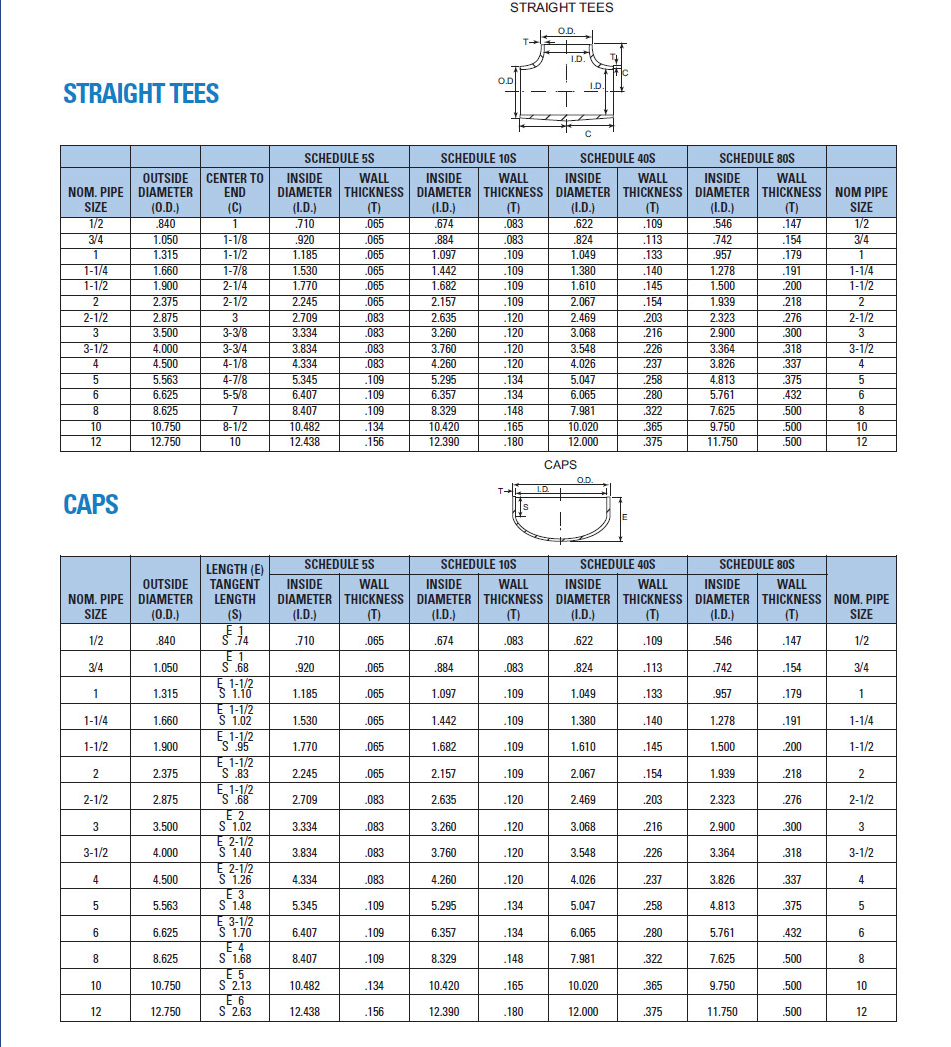
A tee is not defined by one overall number. The main run and branch each need to land in the correct place. On an equal tee, the run and outlet may share the same nominal size, but the drawing still determines how the branch relates to the main line. On a reducing tee, the branch size must be stated separately from the run.
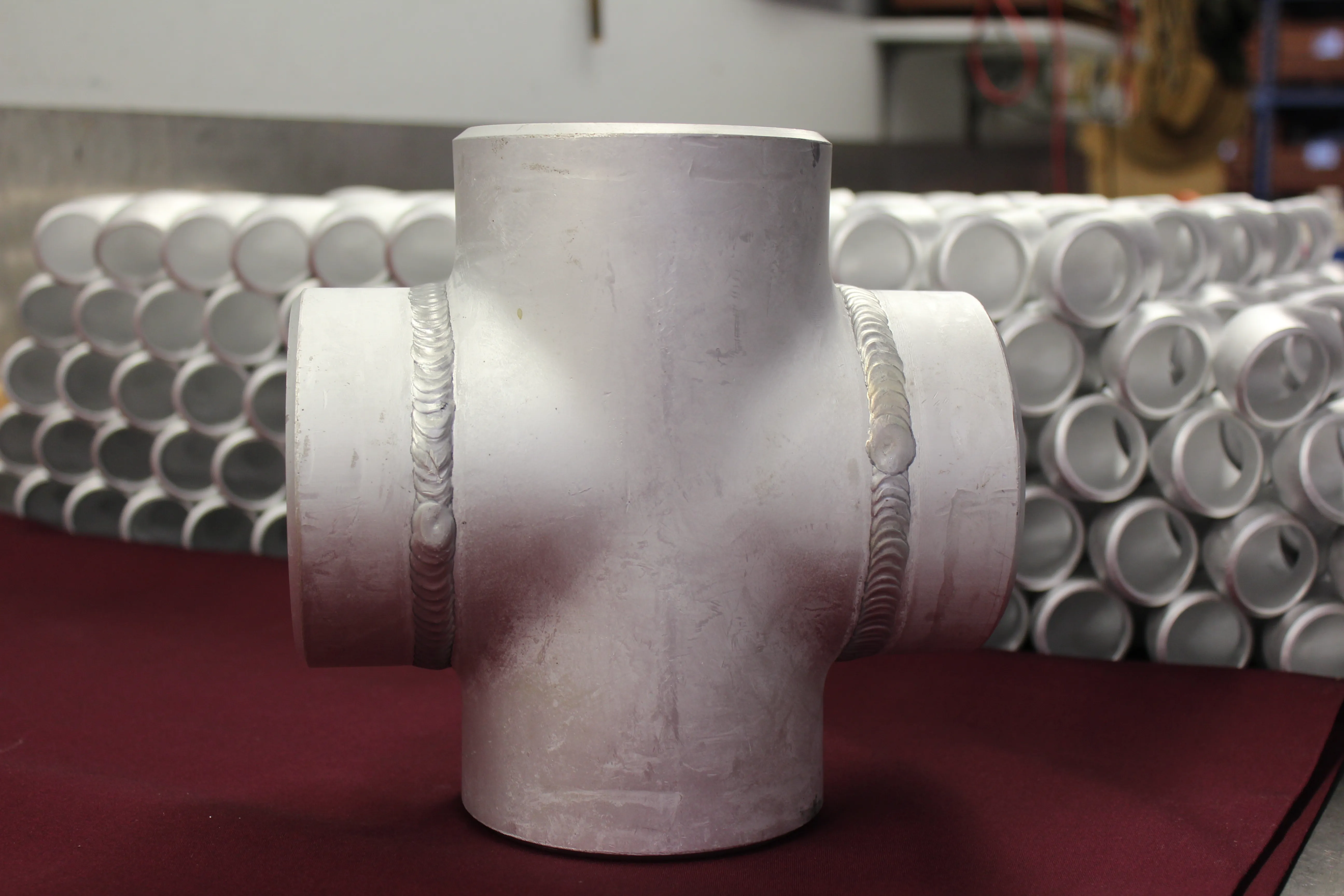
When reviewing a tee chart, identify which dimension belongs to the run and which belongs to the outlet. That distinction matters when the branch connects to a valve, nozzle, support, or another spool with little adjustment room. For a cross, confirm each outlet orientation as well as the centerline dimensions, especially when it forms part of a fabricated assembly.
The tee and cap chart gives a clear reference for common shapes. For a custom tee, add a sketch that shows branch angle, orientation, required straight lengths, any special bevel or machining, and the dimensions that cannot vary. That is far more useful than a line item that only says “aluminum tee.”
Use reducer length and orientation together
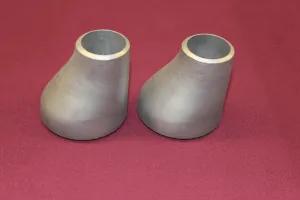
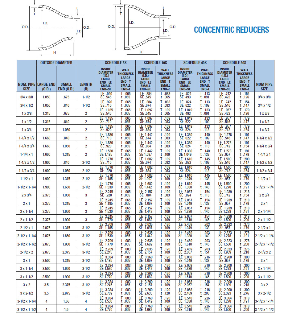
A reducer changes between two pipe sizes, so it needs both sizes in the description. A concentric reducer keeps the pipe centerline aligned. An eccentric reducer keeps one side aligned and shifts the opposite side. The correct choice depends on the piping orientation and the installation need, not just the two diameters.
In addition to the large and small nominal sizes, review the end-to-end length and the reducer orientation. An eccentric reducer installed with the wrong flat orientation can create a drainage, venting, clearance, or alignment issue. State the orientation on the drawing instead of relying on an assumption made from the part name.
The concentric and eccentric reducer charts help establish the standard reference dimensions. If either end must match existing pipe, include the actual wall or schedule and the end-preparation details in the request.
Read the chart with the drawing beside it
A dimension chart is most useful when it is read beside the drawing that defines the assembly. The chart tells you the standard fitting geometry for a selected size and style. The drawing tells you where that geometry must sit, which end joins which component, and whether an orientation, straight length, or clearance controls the finished result. Neither document does the other’s job.
For a replacement, do not begin with a photograph alone. Record the fitting type, nominal size, wall or schedule, and the key layout dimension from the existing installation. Then compare those details with the drawing or line information. A fitting may look like a 90-degree elbow, but the distinction between long-radius and short-radius geometry changes the takeoff enough to matter in a constrained spool.
For new work, trace the dimension from a fixed reference point such as an equipment nozzle, flange face, or established centerline. Check where each fitting end will land after allowing for the next component and the required welding space. This is especially important around valves, supports, pumps, tanks, and bulkheads, where a small unreviewed difference can turn a standard part into a field modification.
When a drawing identifies a dimension as critical, keep it attached to the request rather than translating it into a general part description. The sales and fabrication review is more reliable when the original relationship, units, and reference points stay visible.
Common dimension mistakes that slow a fitting request
One common mistake is treating a nominal size as an actual outside diameter. Nominal pipe size is a system designation, so the mating outside diameter and wall must still be checked. Another is using a general reference dimension as if it approves a nonstandard part. Reference charts are valuable for understanding a likely shape, but an approved project drawing governs a custom offset, special branch location, unusual bevel, or added straight length.
It is also easy to omit the branch dimension on a reducing tee or the orientation on an eccentric reducer. Those missing details can produce a quotation for a part that is technically plausible but wrong for the layout. State both ends of a reducer, both the run and branch of a tee, and the orientation that matters to the piping run.
Finally, avoid separating the material requirement from the dimensional requirement. “Aluminum elbow” is not a complete description of an elbow to be welded into an industrial line. Tie the alloy and temper, wall or schedule, end preparation, quantity, and applicable standard to the geometry in the same request. That gives everyone reviewing the job a single, usable picture of what must fit.
Do not let wall, alloy, and ends become afterthoughts
Dimension charts establish shape, but they do not replace the rest of the fitting requirement. The fitting must match the pipe wall or schedule at the welding ends, the specified alloy and temper, the required end preparation, and any inspection or documentation requirement. Those details affect fit-up, fabrication planning, and the materials that should be reviewed for the job.
For factory-made wrought butt-weld fittings, ASME B16.9 covers overall dimensions, tolerances, ratings, testing, and markings for sizes from NPS 1/2 through NPS 48. Aluminum welding fittings may also need to meet the applicable ASTM B361 specification. The standard reference should support a complete callout, not stand in for one.
For aluminum work, review the required alloy with the fitting geometry. Aluminum Pipe Fittings lists 5086 H32 and 6061 T6 alloy information alongside its fitting range. If the job has a material specification, traceability need, unusual service condition, or a custom geometry, include it with the first request.
A practical dimension-check sequence
Before a purchase order or fabrication release, work from the connection outward. Start by confirming the fitting type, then compare its nominal size or sizes to the mating pipe. Next, identify the chart dimension that establishes the layout, such as center-to-end or end-to-end length. Then confirm the wall, alloy, end detail, and any drawing-controlled orientation.
This sequence catches the common error of confirming a catalog shape without confirming the conditions around it. It also makes it easier to compare quotes, since each supplier is working from the same requirements instead of filling in different assumptions.
How Aluminum Pipe Fittings can help
Aluminum Pipe Fittings can review a fitting request as part of the full piping package, including related pipe, elbows, tees, reducers, flanges, dimensions, and custom requirements. The listed butt-weld range includes common configurations, while custom fittings, flanges, and pipe can be reviewed when a standard chart does not resolve the need.
Start with the aluminum butt-weld fitting range, use the relevant dimension chart, and send the drawing or written requirement through the quote request page. A complete request gives the sales team a practical basis to review the right fitting path.
Frequently asked questions
What does center-to-end mean on a pipe fitting?
Center-to-end is the distance from the fitting centerline to the end of a connection. On an elbow it tells the installer where the direction change lands. On a tee, it helps establish the run and branch takeoff needed to lay out adjoining pipe.
Does pipe schedule change the overall dimensions of a butt-weld fitting?
Schedule or wall thickness is essential for matching the fitting to its pipe, but it is not a substitute for the fitting geometry. Confirm both the listed center-to-end or end-to-end dimension and the required wall or schedule before releasing an order.
How are reducer dimensions written?
A reducer should identify both nominal pipe sizes, the reducer style, the wall or schedule, the alloy and the connection requirement. A concentric reducer keeps the centerline aligned, while an eccentric reducer keeps one side aligned.
What should I send when a fitting dimension is custom?
Send a drawing or clear sketch with overall dimensions, centerlines, straight lengths, end details, alloy, wall requirement, quantity and delivery need. State which dimensions are critical to fit-up so the request can be reviewed against the full assembly.