A pipe fitting takeoff chart is the working bridge between a piping drawing and a purchase request. It turns lines, symbols, notes and dimensions into a list that another person can check, price and supply. The best takeoff does not merely count elbows. It makes the requirements visible: what the part is, where it belongs, what it connects to, and which details still need confirmation.
That discipline matters with aluminum pipe work because a fitting name alone does not settle the alloy, wall, end preparation, dimensions or fabrication requirement. This guide explains how to build a practical takeoff from drawings without treating a general chart as a substitute for the approved project documents.
Start with the drawing set and its revision
Before counting anything, identify the drawing number, revision and issue status. A takeoff tied to an earlier revision can look complete while quietly missing a moved branch, added flange or changed pipe size. Mark the revision at the top of the worksheet and keep the related line list, material class, notes and bill of materials with it.
Then define the scope. Is the list for one spool, one line, one equipment tie-in or an entire package? Work one defined area at a time. This makes it much easier to find a missing item later and avoids adding the same connection from both a plan view and an isometric drawing.
Where a project supplies an isometric, use it as the route map and cross-check it against the supplied material list. Training guidance for piping material preparation calls for a bill of materials to list the components shown on the drawing, including a description, size, material specification or standard, unit and quantity. That is a useful baseline, not a reason to ignore project-specific notes.
Set up the columns before you count
A clear chart prevents a familiar fitting from turning into an incomplete line item. Put the drawing or spool reference first, then add columns for item number, component type, nominal size, schedule or wall, alloy or material, end connection, applicable standard, quantity and notes. If the job has a purchasing code or item code, add that too.
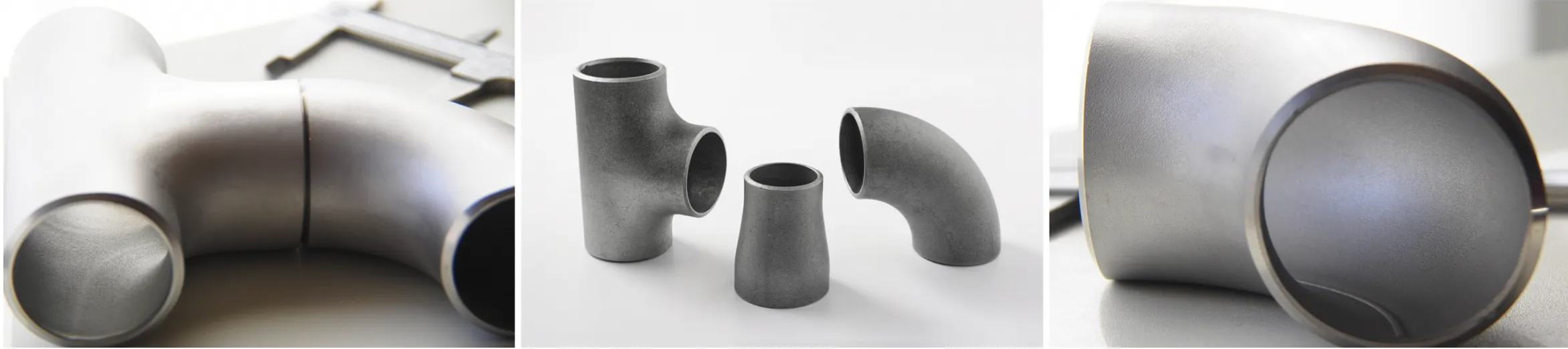
For pipe, record the length separately from the fitting count. For fittings, identify the geometry rather than writing a broad description such as “elbow.” A useful elbow line identifies the angle, long- or short-radius requirement when relevant, nominal size, wall, alloy and end preparation. A reducer line identifies both ends and whether the geometry is concentric or eccentric. A tee line identifies the run and branch sizes.
This structure creates a list that can be reviewed without asking someone to reconstruct the drawing from memory. It also shows which blanks need a decision before a supplier is asked for a price.
Trace one flow path at a time
Choose a logical starting point, such as an equipment nozzle, a flange, a line break or the first connection on a spool. Trace the route in one direction. Each time the route changes direction, branches, changes size, terminates or connects to equipment, record the component that makes that change happen.
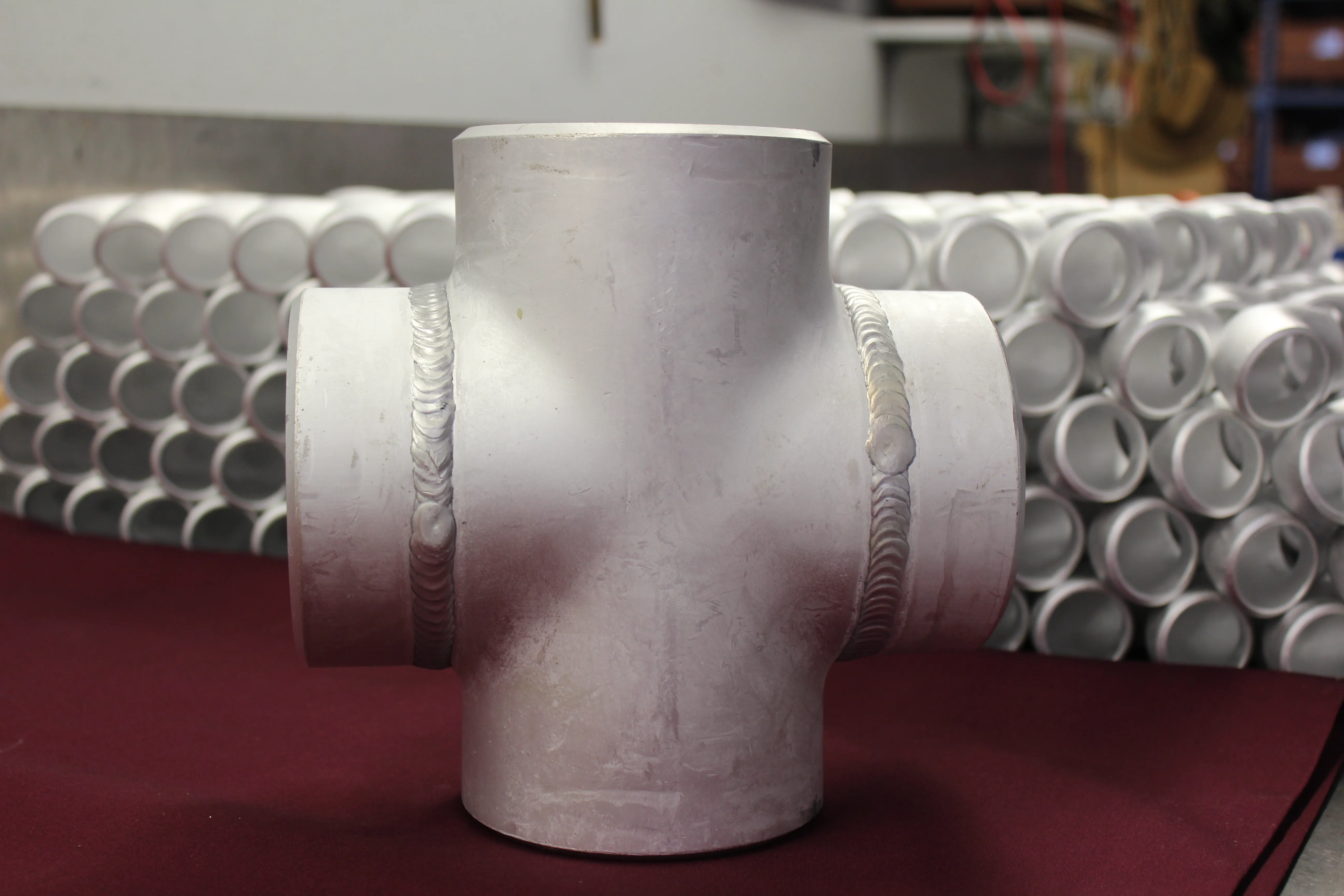
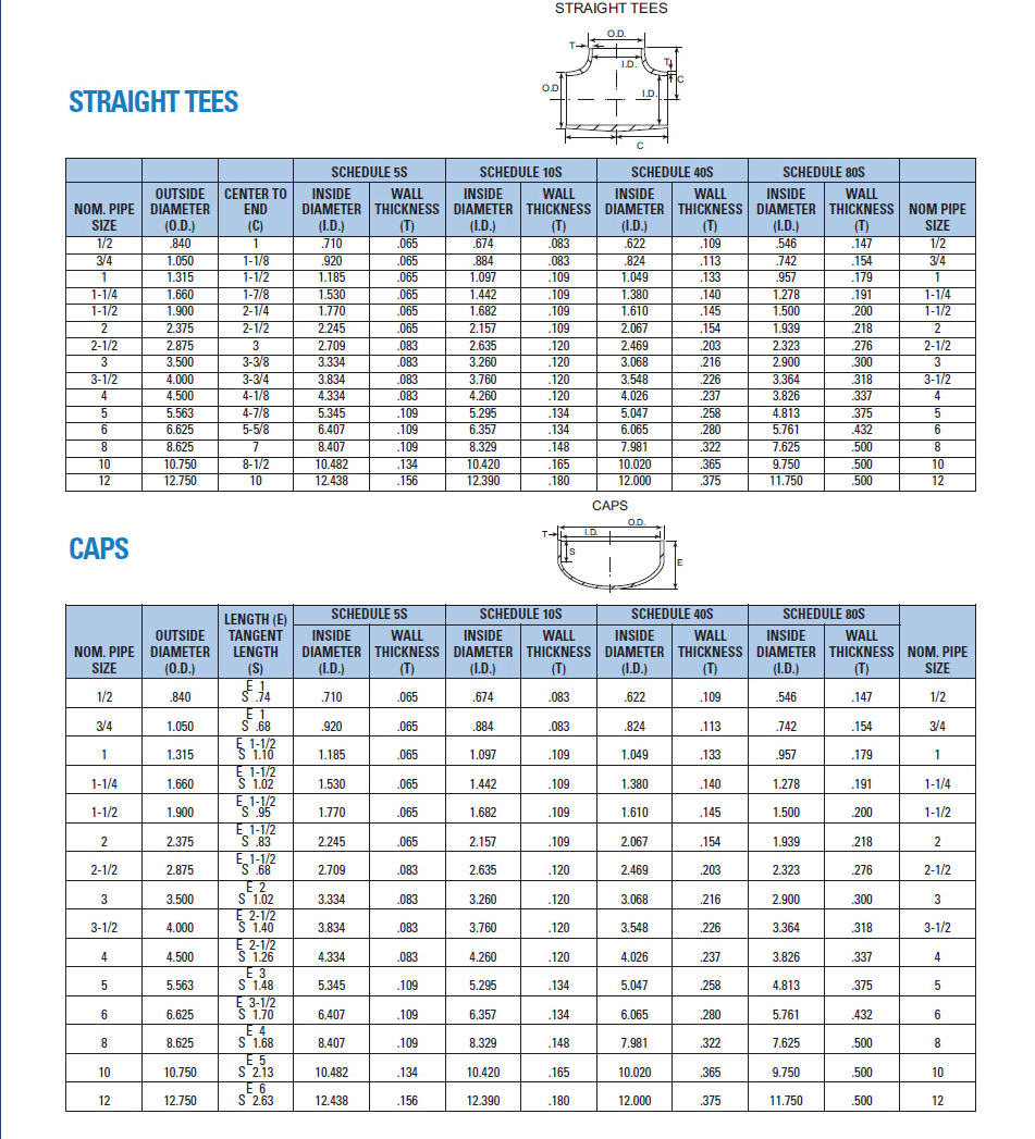
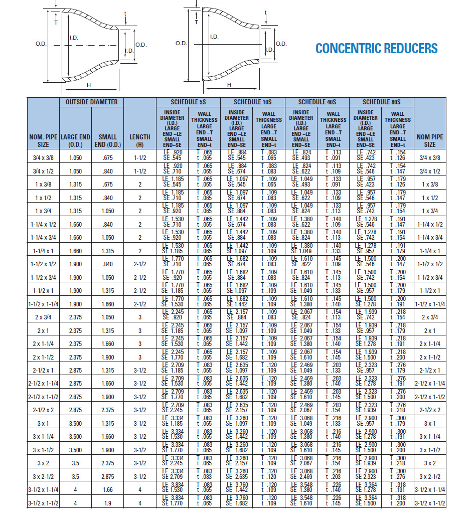
Count fittings from the connection, not from a visual impression. A change in direction may be a 45-degree elbow, 90-degree elbow, return bend or fabricated offset. A branch may be an equal tee, reducing tee, cross, outlet fitting or a custom fabricated piece. A size change may need a concentric reducer or an eccentric reducer, depending on the required orientation. The site’s fitting dimension charts and pipe fitting dimensions guide help organize an early review of those geometries.
Use a highlighter, digital markup or a simple checkmark only after the item is entered. The point is not the colour. It is to leave an auditable path through the drawing so a reviewer can see what was counted and what still requires clarification.
Separate fitting quantity from cut length
A material takeoff answers how many components are needed. A fabrication cut list answers how much pipe must be cut into individual pieces. They connect, but they are not interchangeable. A drawing may show a center-to-center route dimension while the actual cut pipe length depends on the dimensions of the fittings at each end, the connection type and the project’s fabrication instructions.
For factory-made wrought butt-weld fittings, ASME B16.9 covers overall dimensions, tolerances, ratings, testing and marking for the covered fitting range. Use the applicable standard, manufacturer data and project documents for the exact component being considered. Do not pull a takeout value from an unrelated material, radius or fitting style and assume it applies to an aluminum assembly.
Threaded, socket-weld and flanged connections each add their own relationship between pipe and fitting. That is why the chart should identify the connection method from the start. It lets the fabricator or supplier see when the listed pipe length needs another dimensional check rather than treating the line as ready to cut.
Check material and connection details while they are visible
It is tempting to collect every quantity first and fill in the material later. That often creates a list of generic shapes that cannot be compared or quoted reliably. Record the alloy, temper, wall or schedule and end condition when you first find the item on the drawing or material class.
For aluminum welding fittings, ASTM B361 describes factory-made wrought aluminum and aluminum-alloy welding fittings, including butt-welding and socket-end parts made to applicable dimensional standards. The project requirement decides whether it applies, but the reference is a useful reminder that material specification and fitting geometry belong together.
Use the site’s aluminum alloy information as a starting point for the listed 5086 H32 and 6061 T6 fitting materials. The final callout still needs to follow the drawing, service requirements, joining procedure and any documentation requirement. “Aluminum” is not enough detail for a dependable takeoff line.
Review the items that are easiest to miss
Most takeoff mistakes occur at transitions. Recheck every branch, pipe-size change, equipment connection and line end. A reducer may be easy to overlook if it is drawn close to a flange. A tee may need a reducing branch even if the run appears to stay the same size. A cap, blind flange, stub end, gasket or companion flange may live in a note or bill of materials rather than the main route drawing.
Flanged connections deserve a separate pass. Record the flange type, nominal size, alloy, pressure class, facing, bore, drilling and mating component where the project identifies them. The aluminum flange range and the pipe flange types guide can help translate the drawings into a structured request, but they do not replace the project specification.
Finally, look for custom conditions: nonstandard dimensions, special branch orientation, unusual straight lengths, inspection, material certificates, machining, or fabrication notes. These are not “miscellaneous” details. They can change whether the right path is a stock fitting, a modified part or a custom fabricated component.
Common takeoff mistakes to avoid
Combining unlike fittings on one line. Two elbows with the same nominal size may still differ by angle, radius, wall, alloy or end condition. Keep the details that control fit and price visible. A short description may make a worksheet look tidy, but it forces someone else to guess what the job actually needs.
Reading nominal size as the complete dimension. Nominal pipe size identifies an important part of the connection, not every physical detail. The schedule or wall, center-to-end dimension, bore, end preparation and mating component can all matter. This is especially important where a new fitting must align with an existing spool or piece of equipment.
Using a reference chart as final fabrication approval. Dimension charts are helpful for planning and for spotting a question early. They do not override the approved drawing, project standard or manufacturer information for the exact part. If the installation depends on a particular straight length, orientation or connection, put it on the takeoff and attach the drawing instead of leaving it implied.
Forgetting the quote conditions. A correct material list can still lead to an incomplete quote if it leaves out quantity, delivery destination, needed-by date, inspection needs or documentation. Those requirements belong with the component list because they affect how the supplier evaluates the request.
Counting a part twice. When a plan, isometric and bill of materials all describe the same assembly, the same elbow or flange can appear in more than one place. Work from a defined primary drawing and use the others as a check. A marked-up route makes duplicates easier to find before the list reaches purchasing.
A final peer check is worthwhile on work with multiple sizes, changing materials or custom fabrication. A second reader can follow the marked route against the chart and identify a missing branch, conflicting dimension or incomplete material callout before it becomes a procurement delay.
Turn the chart into a quote-ready package
Before sending the takeoff, group the lines so like items can be checked together, then compare the total against the drawing one more time. Confirm that each line has a quantity and that each component can be distinguished from a similar-looking item. If the project uses multiple alloys, schedules or end types, keep them on separate lines rather than combining them under one general description.
Attach the marked drawing or bill of materials with the chart. Include the delivery location, required date, quantity basis and any documentation requirement. If the request includes pipe, fittings, flanges and fabricated work, send it as one assembly package. That lets the review account for the relationships between the parts instead of treating each fitting as an isolated purchase.
How Aluminum Pipe Fittings can help
Aluminum Pipe Fittings supplies 5086 H32 and 6061 T6 aluminum fittings, with stocked sizes from 1/2 in. through 8 in. and custom fittings, flanges and pipe available up to 48 in. When a takeoff includes more than one part type, the team can review the fitting geometry, alloy, wall, dimensions and connection requirements together.
Use the aluminum butt-weld fitting range to start the component review, check the relevant dimension charts, then send the marked drawing and takeoff through the quote request page. A complete package gives the team a clearer basis for a useful quote.
Frequently asked questions
What is a pipe fitting takeoff chart?
A pipe fitting takeoff chart is a controlled list of the pipe, fittings, flanges and related connection details required by a drawing. It should identify the fitting type, size, material, wall or schedule, end condition, quantity and drawing reference so the list can be checked and quoted accurately.
What is the difference between a material takeoff and a cut list?
A material takeoff totals the components needed to buy or price the work. A cut list focuses on individual pipe pieces and their cut lengths for fabrication. A project may need both, but a material takeoff should not be treated as a cut list without confirming the applicable fitting dimensions and fabrication allowances.
Do fitting dimensions change the pipe takeoff?
Yes. A center-to-center drawing dimension is not automatically the length of pipe to cut. The fitting geometry, connection method, bevel or thread engagement, and required fabrication allowance can all change the cut length. Use the applicable dimensions for the exact fitting and project requirements.
What should be included in an aluminum pipe fitting takeoff request?
Include the drawing revision, line or spool reference, fitting type, every nominal size, alloy, schedule or wall, end connection, quantity, standards or documentation requirements, delivery location and needed-by date. A complete bill of materials or marked drawing helps confirm the full assembly.