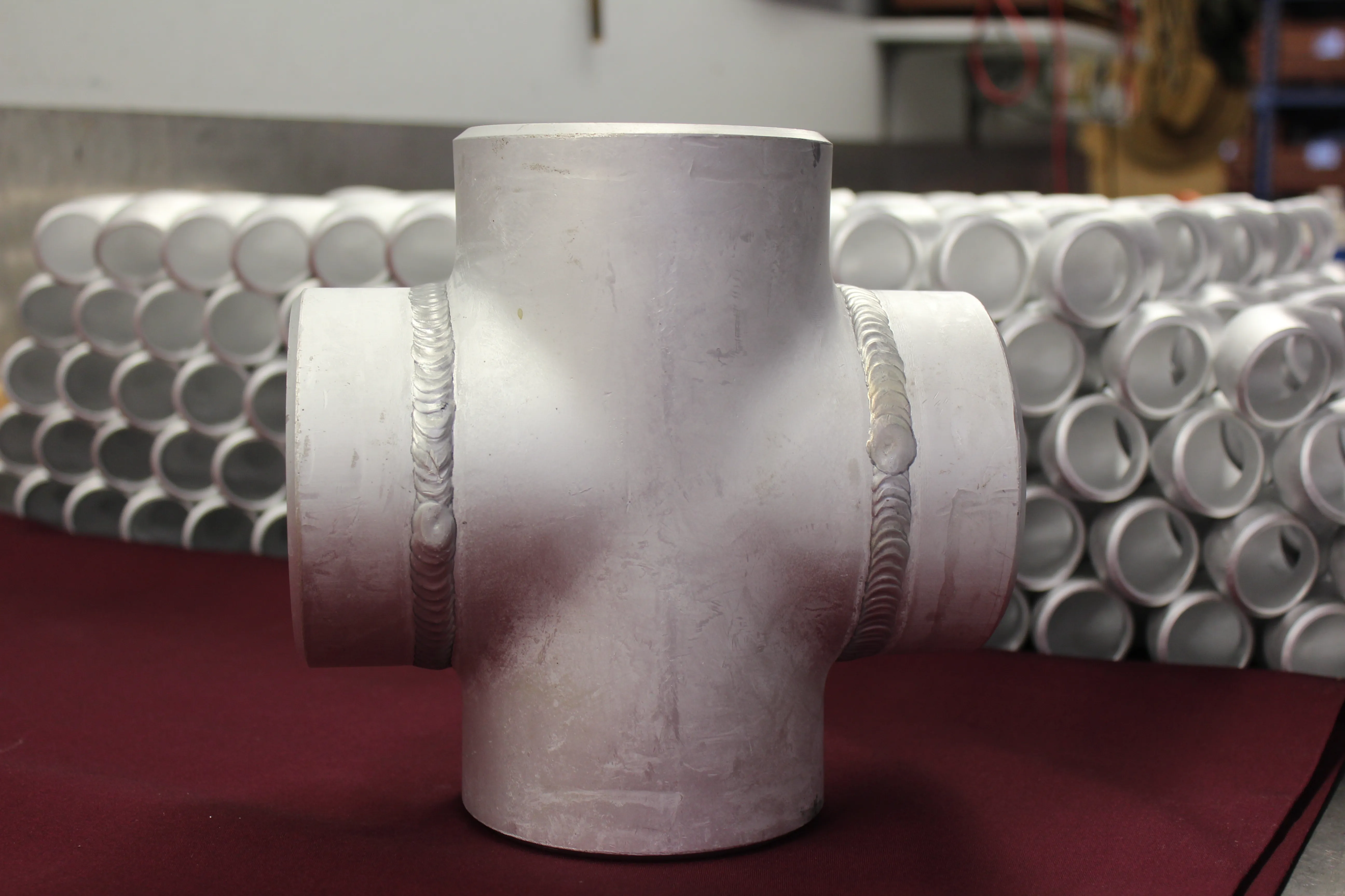
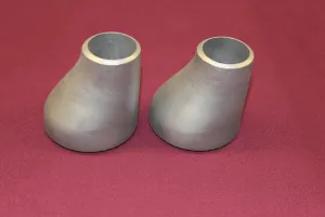
A pipe reducer is a fitting that connects two different pipe sizes in one run. It may transition from a larger main line to a smaller branch, connect to a smaller equipment nozzle, fit a replacement into an existing spool, or keep a piping route practical where the line size changes. The name sounds simple, but the correct reducer is not defined by the two sizes alone.
Before selecting a reducer, identify the geometry, the large and small nominal sizes, the wall or schedule, alloy and temper, end preparation, and the physical relationship the assembly must preserve. For an eccentric reducer, the required orientation belongs in the same conversation. Those details turn a generic transition into a fitting that can be reviewed against the actual piping job.
What a pipe reducer does
A reducer provides a gradual change from one pipe diameter to another. Unlike a short connector or a fabricated workaround, it gives the piping system a defined transition geometry that can be checked against the drawing, neighboring pipe, and applicable fitting standards. In a butt-weld system, the reducer is welded between the larger and smaller pipe ends, so its dimensions and wall relationship matter to the fit-up on both sides.
Reducers are common wherever a pipe route changes size. A larger line may need to approach a smaller valve, pump nozzle, vessel connection, meter run, or downstream branch. The reduction may be part of a new installation, a repair, or a fabricated spool. The reason for the size change affects what must be held in place, such as the pipe centerline, top of pipe, bottom of pipe, a flange face, or an equipment connection.
The fitting does not decide the piping design on its own. A reducer cannot correct an unclear line layout, settle a pump-suction question, or substitute for the service requirements of the system. It is the component used to carry out an approved transition. That is why the surrounding drawing and the information immediately before and after the reducer are as important as the fitting name.
For an initial view of the standard range, the site’s aluminum butt-weld fittings page lists concentric and eccentric reducers with the other common aluminum fitting configurations. Use that as a starting point, then match the final part to the project documents.
Concentric reducers keep the pipe centerline aligned
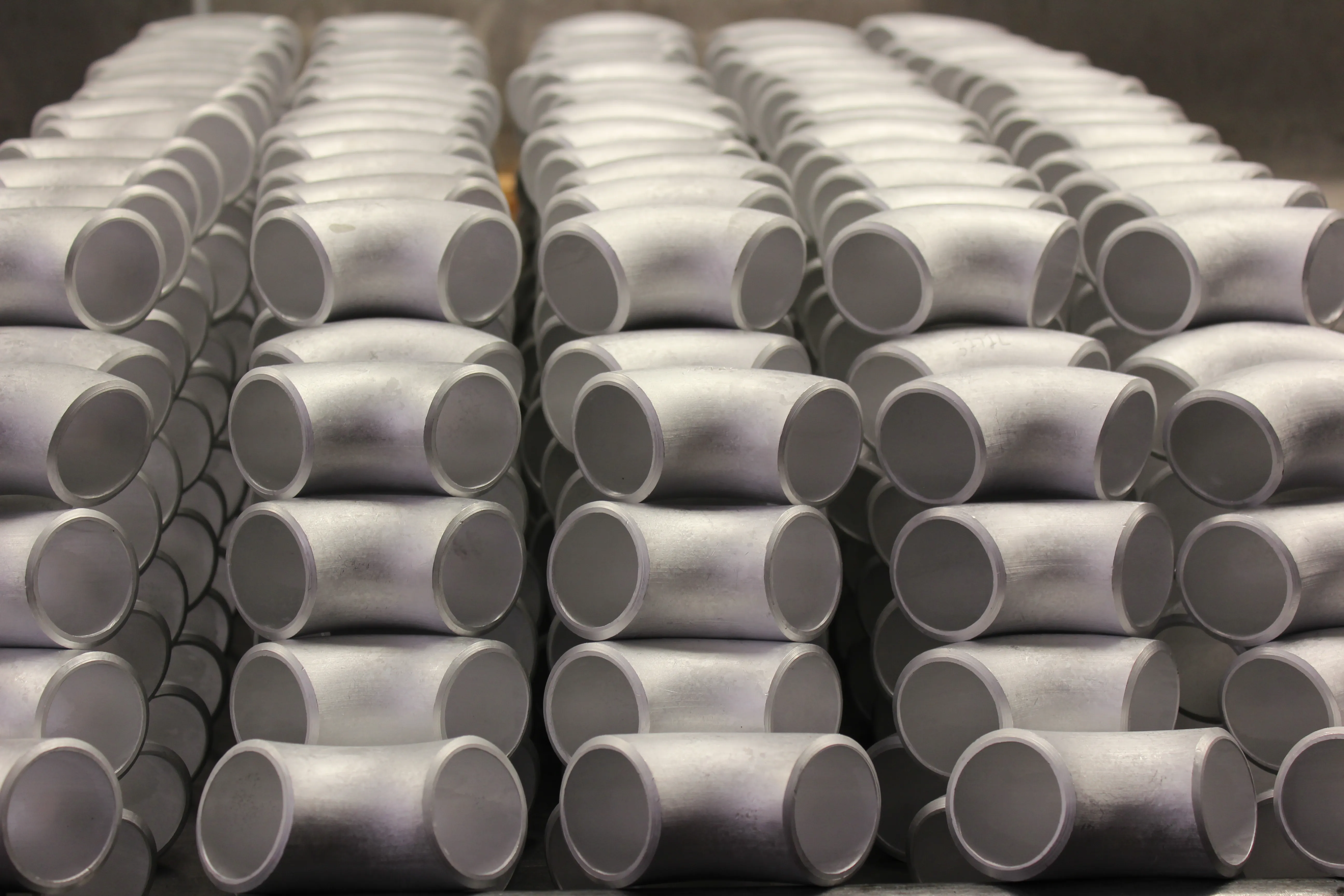
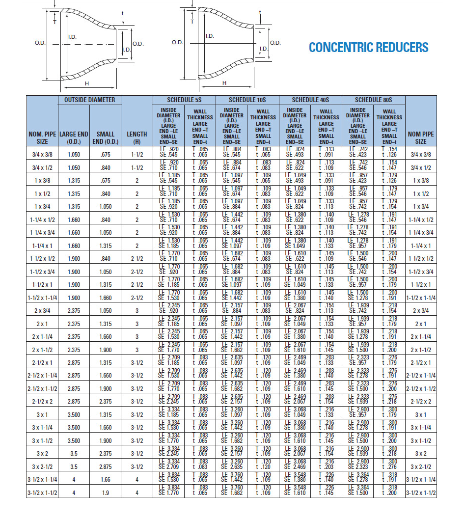
A concentric reducer narrows evenly toward the smaller end. Its tapered shape keeps the centerline of the small pipe aligned with the centerline of the larger pipe. That makes it a familiar choice when the centerline is the relationship the assembly needs to preserve, particularly in many vertical pipe runs and in layouts where the connected components are centered on the same axis.
The centered geometry does not make a concentric reducer automatically right for every application. In a horizontal run, the change in diameter affects the top and bottom profiles of the line even though the centerline remains the same. The service, slope, venting and drainage needs, equipment arrangement, and project drawing determine whether that is suitable.
Start with the two pipe sizes, then check the reducer length and the clearance around the transition. A line may be centered and still interfere with insulation, a support, a valve handle, a nearby spool, or the straight length needed for welding. On replacement work, confirm the existing field dimensions instead of assuming a standard transition will land in the same location as the part it replaces.
The concentric reducer dimension chart is a useful reference for comparing standard sizes and lengths. It helps identify the shape and dimensions to review, but the issued drawing and project requirements remain the final authority for a controlled installation.
Eccentric reducers preserve one outside edge
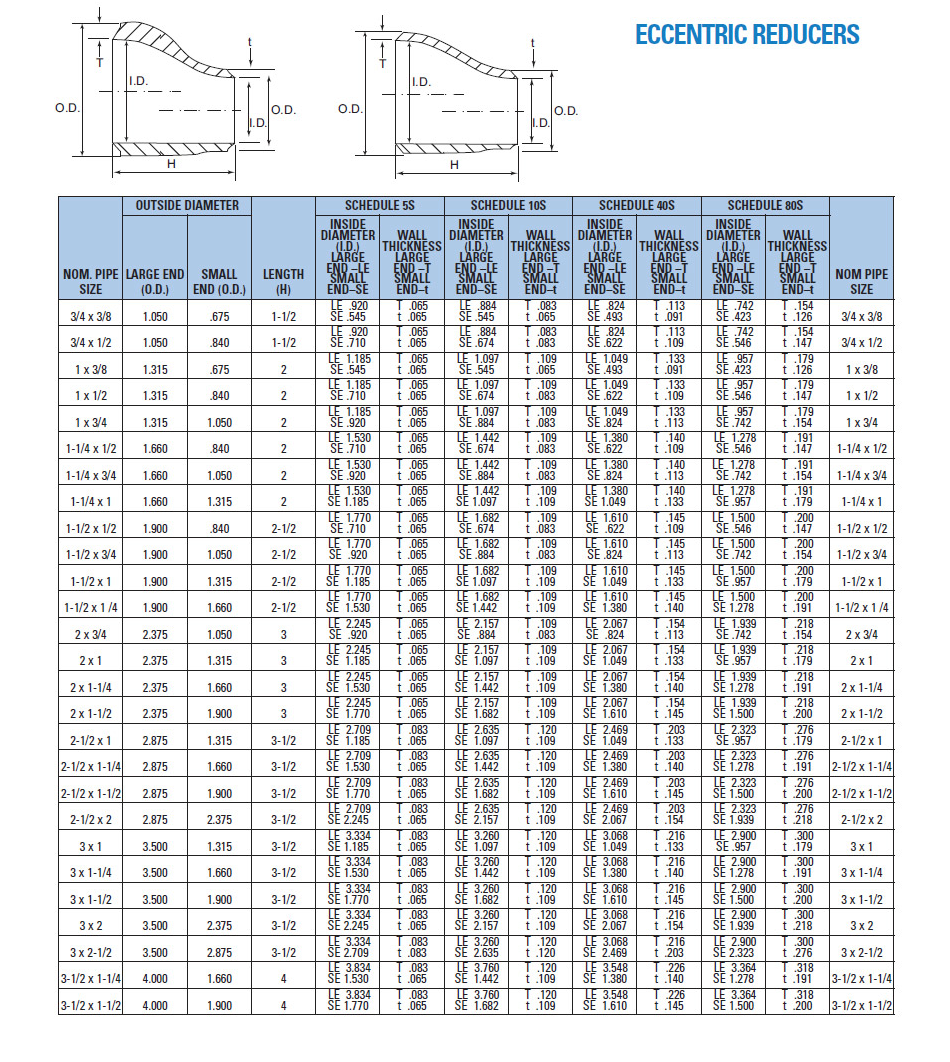
An eccentric reducer has an offset taper. One side is straight, often called the flat side, while the other side slopes toward the smaller pipe. This geometry gives the piping design a way to preserve a chosen outside elevation through the size change, rather than preserving the centerline.
That distinction matters in horizontal pipe runs. A layout may need the top of pipe to remain aligned, the bottom of pipe to remain aligned, or the transition to avoid creating a point where a particular phase can collect. The right orientation depends on what the line carries, the direction of flow, the equipment arrangement, and the approved piping design. An eccentric reducer should not be ordered with its flat-side direction left open.
For example, pump-suction arrangements are often discussed when reducer orientation comes up. The concern is avoiding an unfavorable high point or low point near the suction connection, not applying a phrase from another system without context. Fluid behavior, slope, source elevation, available straight run, and the equipment manufacturer’s requirements can all matter. The drawing or responsible engineering review should identify the final orientation.
An eccentric reducer can also solve a mechanical layout issue. Keeping one outside edge aligned can help maintain a support elevation or connect to a fixed spool where the downstream pipe cannot move. Mark the reducer orientation, the larger and smaller ends, and the flow direction on the drawing so fabrication and installation teams are working from the same intent.
How to read pipe reducer sizes
A reducer callout normally shows the larger nominal pipe size first and the smaller size second. A 6 in. x 4 in. reducer, for example, transitions from a 6 in. nominal pipe size to a 4 in. nominal pipe size. That tells the reader the two ends of the fitting, but it is only the beginning of a complete description.
Next, identify the geometry: concentric or eccentric. For an eccentric reducer, add the required flat-side orientation. Then add the schedule or wall thickness, because a nominal size alone does not define the weld fit-up or the bore relationship. The reducer needs to suit the connecting pipe on both ends. A size match without a compatible wall can create extra work or an unsuitable transition at the weld.
Material belongs with the dimensional callout. Aluminum Pipe Fittings lists 5086 H32 and 6061 T6 aluminum fitting alloys for stock fitting work. The required alloy and temper should follow the piping specification, service environment, joining procedure, and documentation requirements. A reducer described only as “aluminum” is not yet a complete material requirement.
Finally, state the end preparation and any construction, inspection, or record requirements that control the job. For factory-made wrought butt-welding fittings, ASME B16.9 is a useful dimensional reference. For factory-made wrought aluminum and aluminum-alloy welding fittings, ASTM B361 is the specification to review. The contract and project documents determine the actual edition and requirements that apply.
Check more than the two pipe sizes
A reducer can have the correct large and small ends yet still be wrong for the assembly. Review the fitting length, the centerline or outside-edge relationship, wall thickness, welding ends, material, and the space around adjacent components. In a crowded run, the transition may change where a flange, elbow, valve, support, or spool connection lands.
For a standard part, begin with the relevant dimension chart and compare it with the pipe schedule, drawing, and bill of materials. The site separates the concentric and eccentric reducer charts, making it easier to check the intended geometry. The broader fitting dimension charts are useful when the reducer is part of a package with elbows, tees, or caps.
For replacement work, document what is actually in the field. Identify the existing pipe size, wall, outside elevation, end condition, and the fixed points that cannot move. Photos, measurements, spool information, and a marked-up drawing often prevent a standard fitting from being selected for a nonstandard situation.
For custom work, name the dimensions that control the finished result. A special taper, added straight length, unusual wall, required offset, machining detail, or fixed nozzle relationship should be shown rather than left to interpretation. Aluminum Pipe Fittings can review custom fittings, flanges, and pipe up to 48 in., but the fitting needs a clear definition before it can be evaluated accurately.
Common pipe reducer mistakes
The first mistake is treating concentric and eccentric reducers as interchangeable because they connect the same two pipe sizes. They do not preserve the same line geometry. A concentric reducer keeps the centerline, while an eccentric reducer holds one outside edge. Choosing the wrong profile can move the downstream pipe or create an arrangement the drawing did not intend.
The second is omitting the orientation on an eccentric reducer. “Eccentric reducer, 6 in. x 4 in.” describes the taper but not where the flat side belongs. Show the orientation and flow direction on the drawing before fabrication. It is much easier to confirm that information in a quote request than to resolve it after the fitting arrives at the job site.
The third is leaving out wall, alloy, and end details. A reducer is not fully identified by its nominal sizes. The material requirement, schedule or wall, and end preparation affect availability, fit-up, welding, and documentation. Keep those details together in the purchase description.
Finally, do not use a reference chart as final approval for a custom fitting. Charts are useful for standard geometry. They cannot define an unusual taper, a nonstandard offset, a special machining feature, or a reducer’s relationship to a fabricated assembly. When the job is outside the standard range, attach the drawing that shows what must be held.
Prepare a complete reducer request
A clear reducer request helps everyone review the same fitting requirement. Begin by naming the geometry, then list the large-end and small-end nominal sizes. Add the alloy and temper, schedule or wall thickness, end preparation, quantity, delivery location, and needed-by date. Include the required standard and inspection or documentation details when they apply.
For an eccentric reducer, add the flat-side orientation and flow direction. For a replacement or custom part, include the spool drawing, the mating components, and the fixed dimensions around the transition. The more clearly the relationship is shown, the less likely it is that a correct-looking reducer becomes a fit-up problem later.
How Aluminum Pipe Fittings can help
Aluminum Pipe Fittings supplies 5086 H32 and 6061 T6 aluminum fittings from stock in 1/2 in. through 8 in. sizes, including concentric and eccentric reducers. Start with the aluminum pipe reducers page and the published reducer dimension charts, then compare the fitting with the drawing, wall, material, and surrounding pipe.
For a standard requirement, the aluminum butt-weld fitting range provides a practical starting point. For a custom transition, a replacement spool, or a larger package, use the quote request page to send the sizes, alloy, wall, reducer geometry, orientation, drawing, quantity, and delivery timing together.
Frequently asked questions
What is a pipe reducer?
A pipe reducer is a fitting that joins two different nominal pipe sizes in the same run. It creates a controlled transition between the larger and smaller pipe, while the fitting geometry, wall, material, end preparation, and installation orientation still need to match the project requirements.
What is the difference between a concentric and eccentric reducer?
A concentric reducer keeps the centerline through the transition. An eccentric reducer keeps one outside edge aligned and offsets the other side. The drawing, line orientation, service conditions, and adjacent equipment determine which geometry is appropriate.
How are pipe reducer sizes written?
Reducer sizes normally identify the larger nominal pipe size first and the smaller size second, such as 6 in. x 4 in. The callout should also state whether the reducer is concentric or eccentric, along with the required alloy, wall or schedule, end preparation, quantity, and any orientation requirement.
Can a pipe reducer be used to control pressure or flow?
A reducer changes the pipe diameter, but it is not a substitute for a properly designed control device or an engineering review of the system. Pressure, velocity, flow behavior, equipment requirements, and the piping design should be evaluated together before a reducer is selected for a specific service.
What should be included in a reducer quote request?
Include the reducer geometry, both nominal pipe sizes, alloy and temper, schedule or wall thickness, end details, quantity, delivery need, and the drawing or spool information. For an eccentric reducer, show the flow direction and the required flat-side orientation.