Aluminum pipe connectors are easy to describe loosely and difficult to select loosely. The word can mean an elbow, tee, reducer, cap, flange, threaded fitting, socket-weld fitting, or a machined connection. Each makes a different joint, and each must match the pipe, layout, and project requirements around it.
This guide gives buyers, fabricators, and engineers a practical way to identify the right connector before requesting a quote. It focuses on the details that protect fit-up: the job the connection performs, the way it joins, the pipe dimensions it must match, and the information a supplier needs to review the requirement accurately.
Start with the job the connector has to do
Before naming a part, define the change happening in the piping run. An elbow changes direction. A tee creates or combines a branch. A reducer changes diameter. A cap closes an end. A flange creates a bolted connection to equipment or another flanged component. A threaded, socket-weld, or machined connection solves a different mating condition.
That first decision prevents a common mistake: asking for a generic connector when the job actually needs a particular geometry. A 90-degree elbow cannot replace a 45-degree elbow simply because both turn the line. A concentric reducer cannot automatically replace an eccentric reducer because the pipe centerline or bottom alignment may matter. A drawing, line list, or clear description of the mating components is the best starting point.
The site’s aluminum butt-weld fitting range is a useful way to see the common elbows, tees, reducers, caps, and crosses. For a connection that must bolt to equipment or another assembly, the aluminum flange range is the more relevant path. Identify the connection’s job first, then review the product family that fits it.
Choose the connection style before comparing sizes
Connection style controls how the connector interfaces with the rest of the system. Butt-weld fittings join directly to prepared pipe ends. They are often selected where the piping route, wall requirement, and welded assembly need to work together. Threaded and socket-weld fittings use different joint designs and should not be treated as interchangeable with a butt-weld component. Flanges use a bolted joint and add requirements such as pressure class, facing, bore, drilling, gasket, and mating flange details.
For factory-made wrought butt-welding fittings, ASME B16.9 describes overall dimensions, tolerances, ratings, testing, and marking for the covered fitting range. It provides a shared reference for the fitting itself, but it does not replace the project drawing, piping code, or service requirements. The actual connector still has to match the adjoining pipe and the job’s specified materials.
When the request involves aluminum welding fittings, ASTM B361 is a specification to review where it applies. It covers factory-made wrought aluminum and aluminum-alloy welding fittings, including butt-welding and socket-end parts. Use the applicable standard as part of a complete callout, not as a shortcut around missing size, alloy, or end details.
Match nominal pipe size, wall, and fitting ends
Nominal pipe size is only one part of the fit. The connector must also suit the wall or schedule of the pipe it joins. For a butt-weld fitting, that means looking at the prepared ends and the pipe wall together. A component can have the right nominal diameter yet still require review if the wall, bore, or end preparation does not match the mating pipe.
For a reducer or reducing tee, write down every connection size. A 4 in. x 2 in. reducer and a 4 in. x 4 in. x 2 in. tee describe different jobs. Include the schedule or stated wall at each relevant end. This matters because the smaller pipe connection should not be left to assumption, and it is especially important when the assembly has a change in wall, material, or construction requirement.
Use the dimension charts as a planning reference, then check the final requirement against the project documents. Center-to-end dimensions, radius, branch position, and reducer orientation can move the next weld or flange enough to affect a compact assembly. If the job has a nonstandard tangent, special bevel, or machined bore, show it on the drawing rather than trying to describe it as a standard connector.
Know the connector families that solve common piping changes
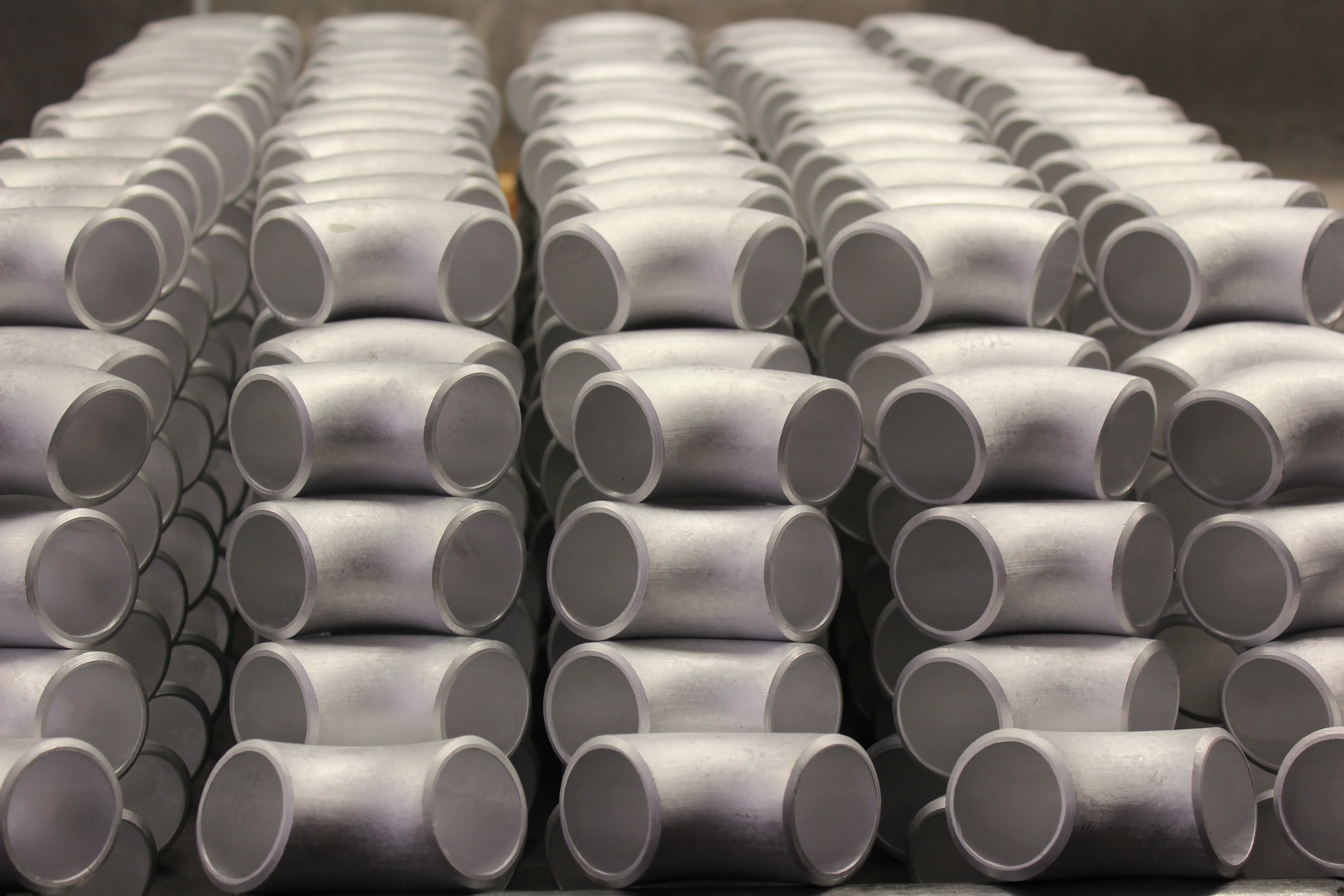
Elbows turn the pipe route. The angle and radius are both essential. The aluminum elbow page and the elbow dimension charts can help establish whether the drawing calls for a long-radius or short-radius part, but the final selection needs to follow the actual layout.
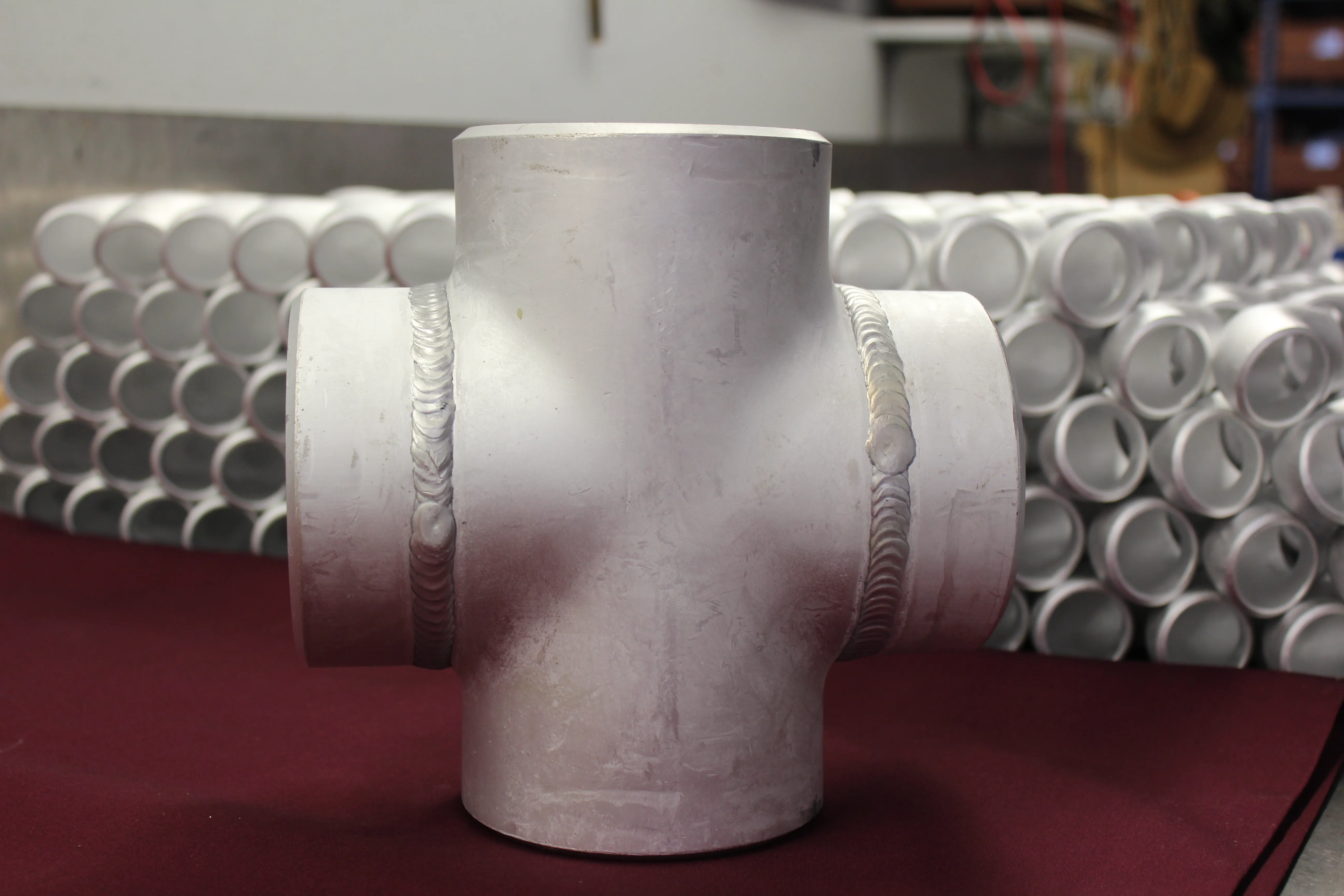
Tees and crosses create branches. An equal tee keeps the same nominal size through the run and branch. A reducing tee has a smaller branch. The tee fitting range and tee and cap chart are useful references, but they do not replace the branch size, wall, orientation, and project drawing.
Reducers join different pipe sizes. A concentric reducer keeps the centerline centered. An eccentric reducer holds one side aligned, which can matter for drainage, elevation, or a specific piping layout. Review both sizes and the required orientation with the concentric or eccentric reducer charts.
Caps and flanges solve different end conditions. A cap closes a pipe end, while a flange creates a bolted mating surface. The connector type should follow the way the assembly must be serviced, inspected, or connected to equipment, not merely what seems closest in stock.
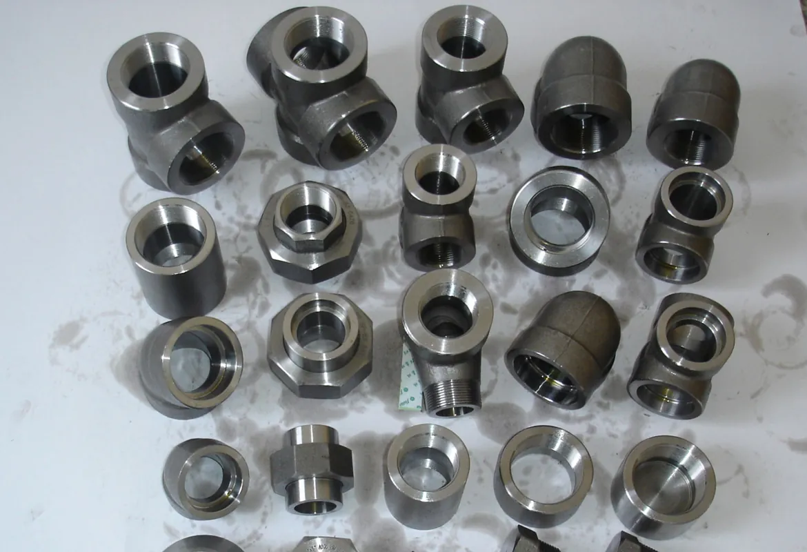
Keep alloy and documentation with the connector request
An aluminum connector needs a material requirement, not just the word “aluminum.” Aluminum Pipe Fittings lists 5086 H32 and 6061 T6 as stock fitting alloys. The right requirement comes from the drawing, service conditions, joining procedure, and project material specification. Include alloy and temper where required with the geometry, size, and wall so the full component can be reviewed as one requirement.
Material certificates, markings, inspection, dimensional verification, or other documentation are also easier to plan before a quote is issued. If the connection is part of a marine, industrial, repair, or fabricated assembly, state the governing standard and documentation need at the start. A supplier can then review the actual scope instead of pricing a simplified description that misses a necessary condition.
The aluminum alloy guide gives a starting point for the listed stock materials. It is still important to use the approved project documents to decide the actual material requirement. A material name cannot substitute for the needed connector geometry or a complete mating-connection description.
Replacement connections need extra evidence
A replacement request often starts with a worn or unmarked component. It is tempting to match it by appearance, but visible shape rarely establishes all of the details that control fit. Measure the nominal pipe size, outside dimensions, thread or bore details, wall where accessible, center-to-end distance, and flange drilling or facing where relevant. Photograph markings and the mating pipe or equipment connection.
Then compare the evidence to the drawing or line information. A replacement may need the same fit-up envelope but a different geometry from what is visible in isolation. The surrounding pipe, clearance, flange face, valve, or equipment nozzle can reveal the critical condition. Sharing that context early gives the supplier a real basis for reviewing the closest standard or custom option.
Build a complete request before asking for price or availability
A complete connector request saves time because it keeps the questions that determine suitability together. It also makes competing quotes easier to compare. Include the connector type, nominal sizes, schedule or wall, alloy, end connection, quantity, drawing, required standard, documentation needs, delivery location, and needed-by date. For a branch or reducer, list every relevant size and orientation.
State any decision that the supplier should not infer. If one end must retain a specific elevation, if a branch needs a particular clock position, or if an existing component cannot move, note it on the drawing. Small details like these are often what separate a connector that is dimensionally plausible from one that actually fits during installation.
For a standard item, start with the fitting range and the relevant dimension reference. For a custom or replacement connection, send the drawing, sketch, photos, and measurements through the quote request page. The team can then review the connector with the complete aluminum pipe, fitting, flange, and fabrication requirement.
When a custom connector review is the safer choice
A standard connector is appropriate when its geometry, material, wall, ends, and applicable specification match the job. A custom review is usually safer when the connection has a special angle, nonstandard center-to-end dimension, unusual wall, added machining, large size, or a requirement to fit existing equipment. The same is true where several components need to work as one fabricated assembly.
Custom review is also helpful when the connector must resolve more than one constraint at once. For example, a replacement may need to preserve an existing flange face while changing the pipe size, or a fabricated spool may need a branch at a specific distance from a support. Those details are difficult to infer from a fitting name. A marked drawing or simple sketch lets the connection be assessed in the context of the finished assembly.
Aluminum Pipe Fittings can review fittings alongside the companion pipe, flanges, and custom fabrication requirements. Giving the full job context early makes it easier to determine whether the standard product path is suitable or whether a more specific connector should be fabricated for the installation.
Frequently asked questions
What is an aluminum pipe connector?
An aluminum pipe connector is the component that joins pipe to pipe, changes direction, creates a branch, changes size, closes an end, or connects pipe to equipment. The correct connector is defined by its geometry, connection style, size, wall, alloy, and the mating components.
How do I choose an aluminum pipe connector?
Start with the job the connection must do, then identify the pipe size, wall or schedule, alloy, end connection, fitting geometry, applicable specification, and any drawing or documentation requirement. A connector should be reviewed with the pipe and component it mates to, not as an isolated item.
Are aluminum pipe connectors available in custom sizes?
Custom fittings, flanges, and pipe are available when a standard elbow, tee, reducer, cap, or machined connector does not match the required geometry. Provide a drawing, dimensions, alloy, wall, quantity, and delivery requirement for a practical review.
What information is needed for an aluminum connector quote?
Include the connector type, nominal pipe size, wall or schedule, alloy, end details, quantity, drawing or sketch, applicable specification, documentation needs, delivery location, and needed-by date. For a replacement, include photos, markings, and measured dimensions of the mating parts.